I saw a recent discussion on how difficult it would be to create a glowing logo for a popular smartphone. And i thought to myself, what a great idea for a DIY project! Here i will show you how to build a simple glowing logo for your favourite product, brand, or even person using an Arduino with some patience.
Prototyping Methods
In order to build a custom case, logo or other glowing ‘thingy’ you need to first decide what ‘container’ you want to build it in (or to design).
Some good prototyping methods:
- 3D printer
- Polymorph
- Wood
- Plastic
- Clay * caution conducts electricity until dry
- Cardboard
Creating a ‘Case’
Image may be NSFW.
Clik here to view.
For this build I chose to use cardboard as I have a cute box available.
I sketched the design first. And then using a sharp exacto knife I cut out the areas I wanted the light to shine through.
Assembly
To do the assembly, I used:
- The case I created
- Small PCB
- 4 pieces of 22 gauge wire
- Some fancy wire ends
- 3x 100 ohm resisors, but 330 would work fine
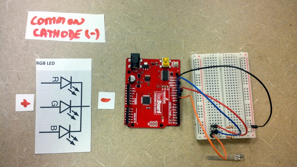
- 2x Common Cathode RGB LED’s (although you could use three if you wanted) and omit the resistors
Image may be NSFW.
Clik here to view.
You need to “recreate” your breadboard on your PCB. Be cautious, some PCB’s have ‘runs’ between the holes to connect them. You need to look very carefully with a bright light to make sure!
Step 1: Solder the long legs together first
Step 2: Solder a black cable to the long legs – this will be your ground
Step 3: Next, solder the 3 remaining RGB LED’s with the ends facing each other in a 1 to 1 fashion
Note: Do not mix and match legs if different sizes (to try and put RGB LED 1’s Green pin with RGB LED 2’s Red pin). It may seem like a cool idea, but the different RGB LED’s internally have different resistances. So what will happen is only one side will light and the other will not.
Step 4: Attached resistors to the three legs. And solder 22 gauge wire to the other end of the resistors
Note: You may want to do these one ta a time and test them on your Arduino’s 5V pin to make sure they are correct and working.
Step 5: Once the electronics are assembled, move them into the case. Popped out the wires through the small hole on the side, And connect to power.
Finished Product
Image may be NSFW.
Clik here to view.
Related Articles: